DRONE SWARM (vErsion 2):
This is the second design revision of my drone swarm. The first revision was more of a way for me to learn the ropes of the different CAD tools and end up with a test board. Its goal was to be an initial test, and it was unrealistic in terms of weight, processing power and battery life. This new revision is ready for fabrication and solves many of these problems .
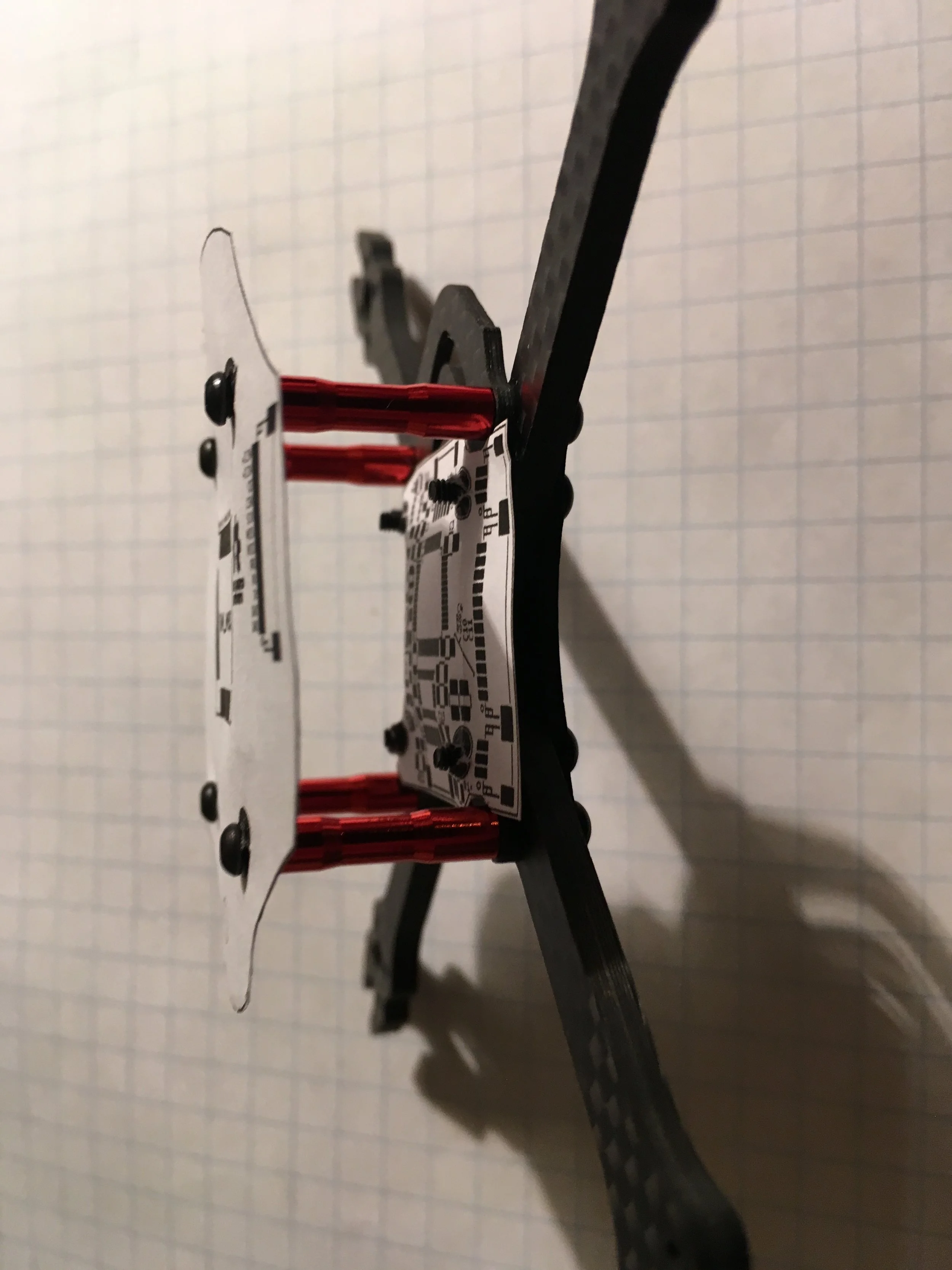
This version of the drone consists of only two circuit boards. One handles all of the radio communication, and only has a GPS and radio module, while the other is the brains of the operation, flying the autonomous path programmed onto a MicroSD card. The details of the two boards are listed below.
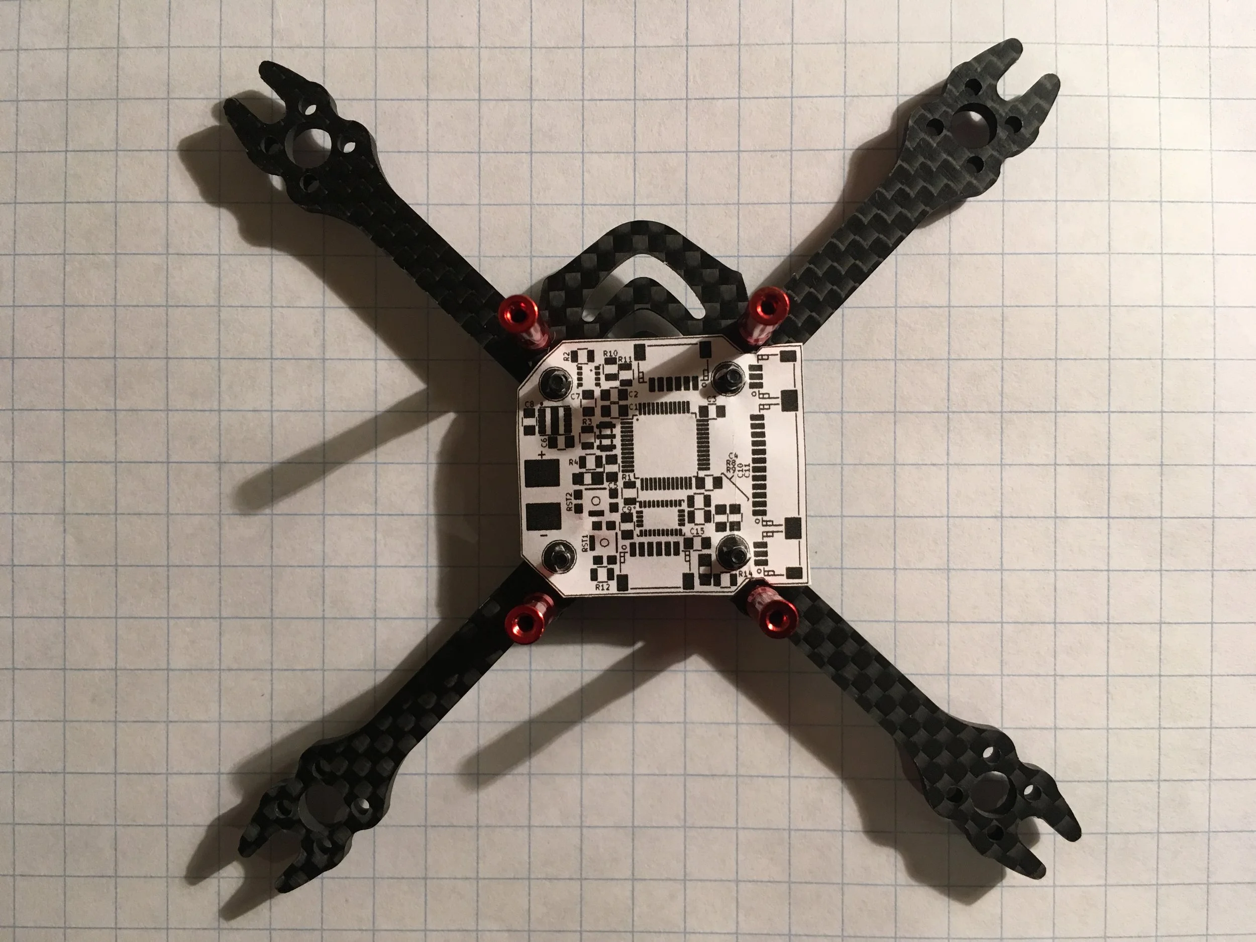
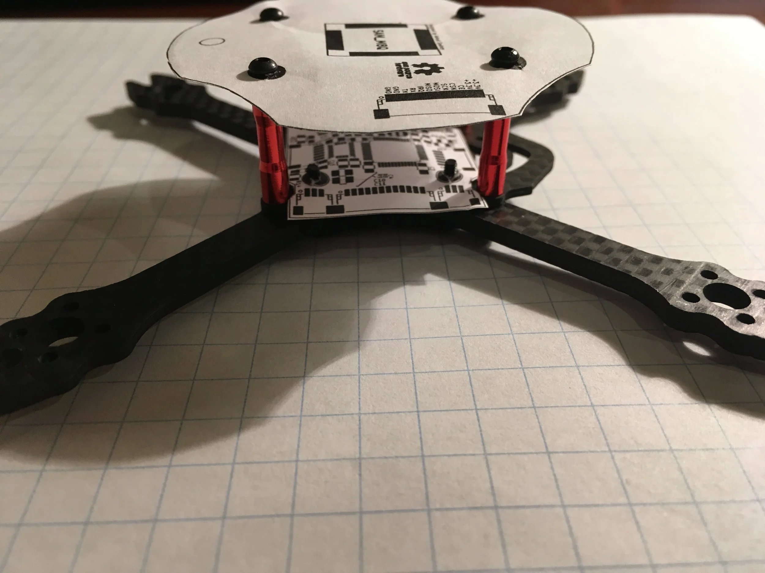
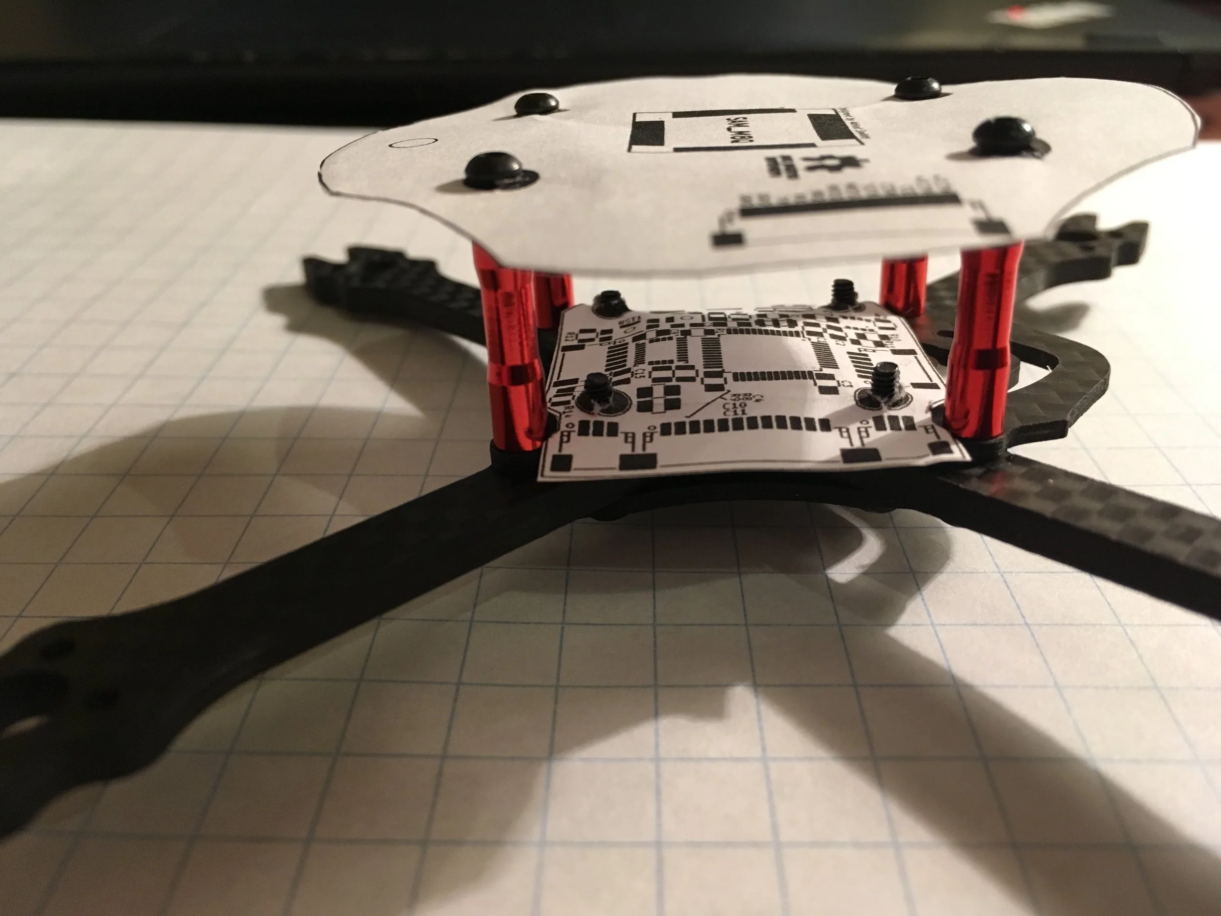
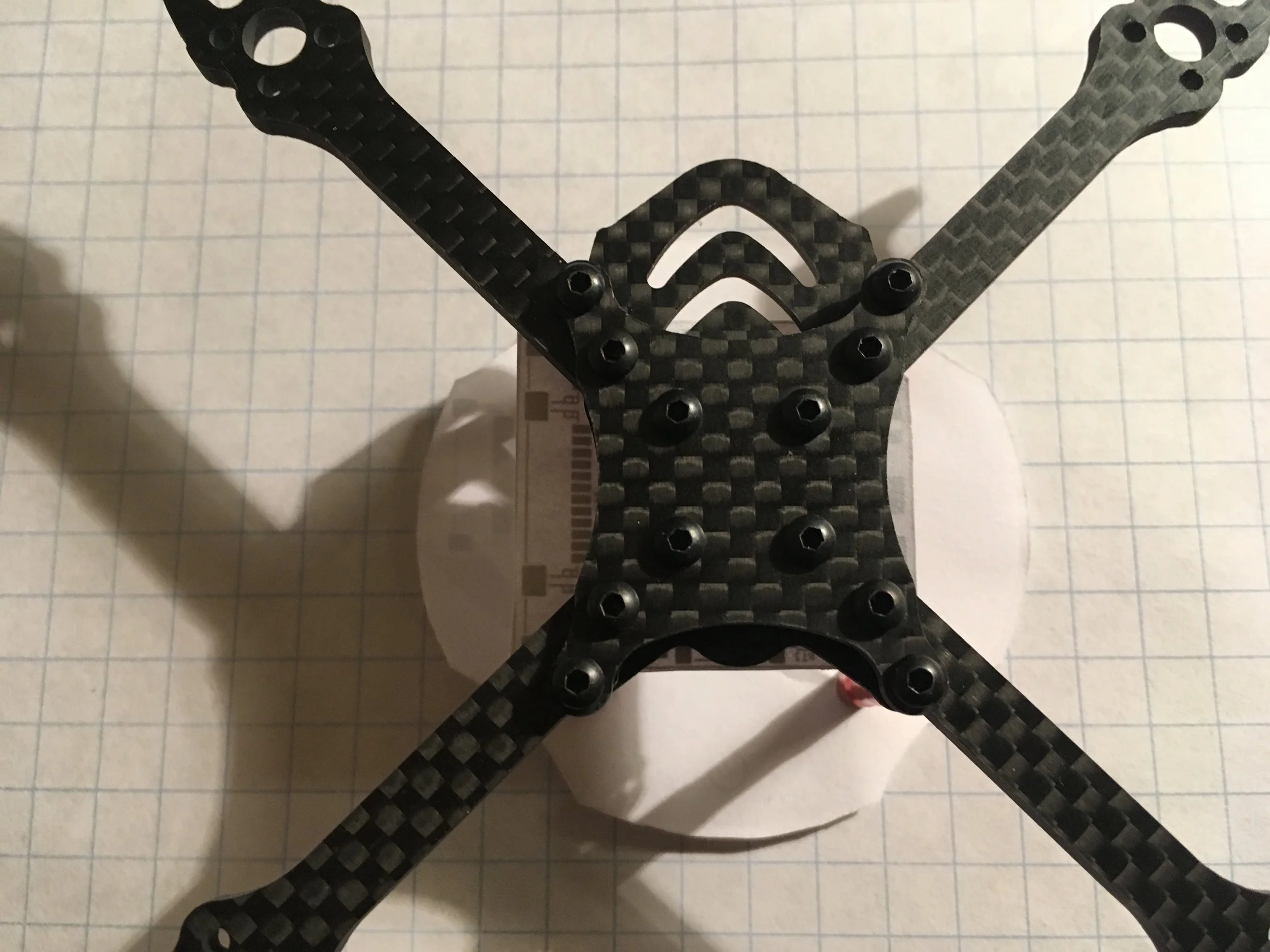
I designed the drone around this commercially available frame. This means that there are a variety of parts already available for this form factor such as motors, propellers, and motor control boards. Thus I can buy and assemble most of the drone with off the shelf components, and simply add in my control and radio boards, as opposed to designing the entire drone from scratch.
The new version is split into two circuit boards.
top Board: (Radio)
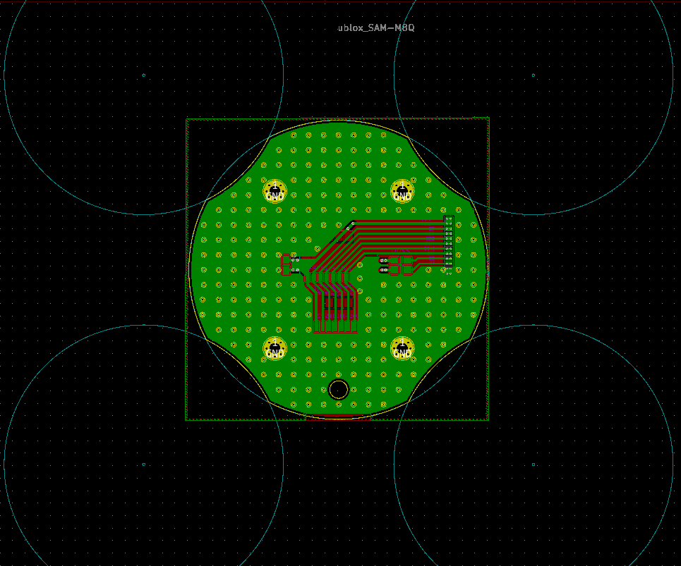
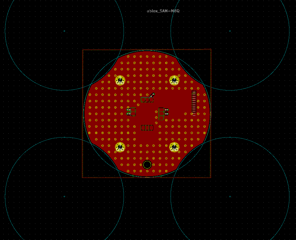
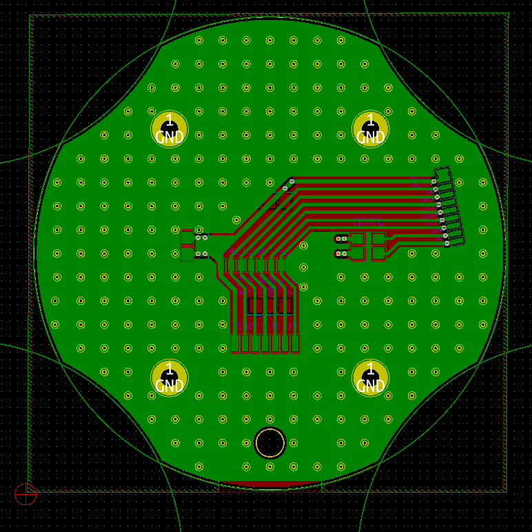
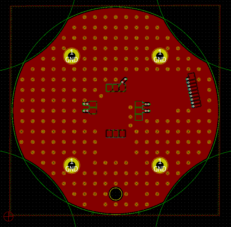
This board serves only two functions: a GPS and a radio receiver/transmitter. It is designed to have the absolute minimum number of components and a very simple circuit to minimize electrical noise. Almost all of the PCB traces and components are on the bottom side, meaning that there is a large unbroken “ground plane” on the top. This boosts the gain of the GPS antenna, and improves the accuracy of the readings.
Features:
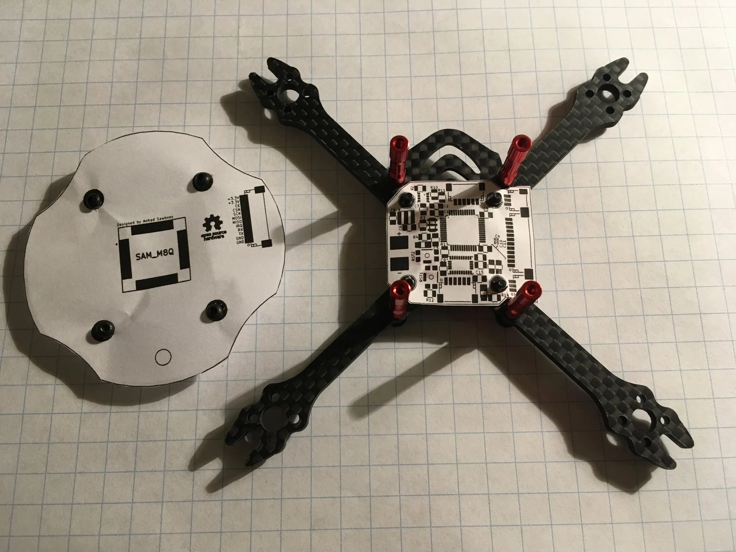
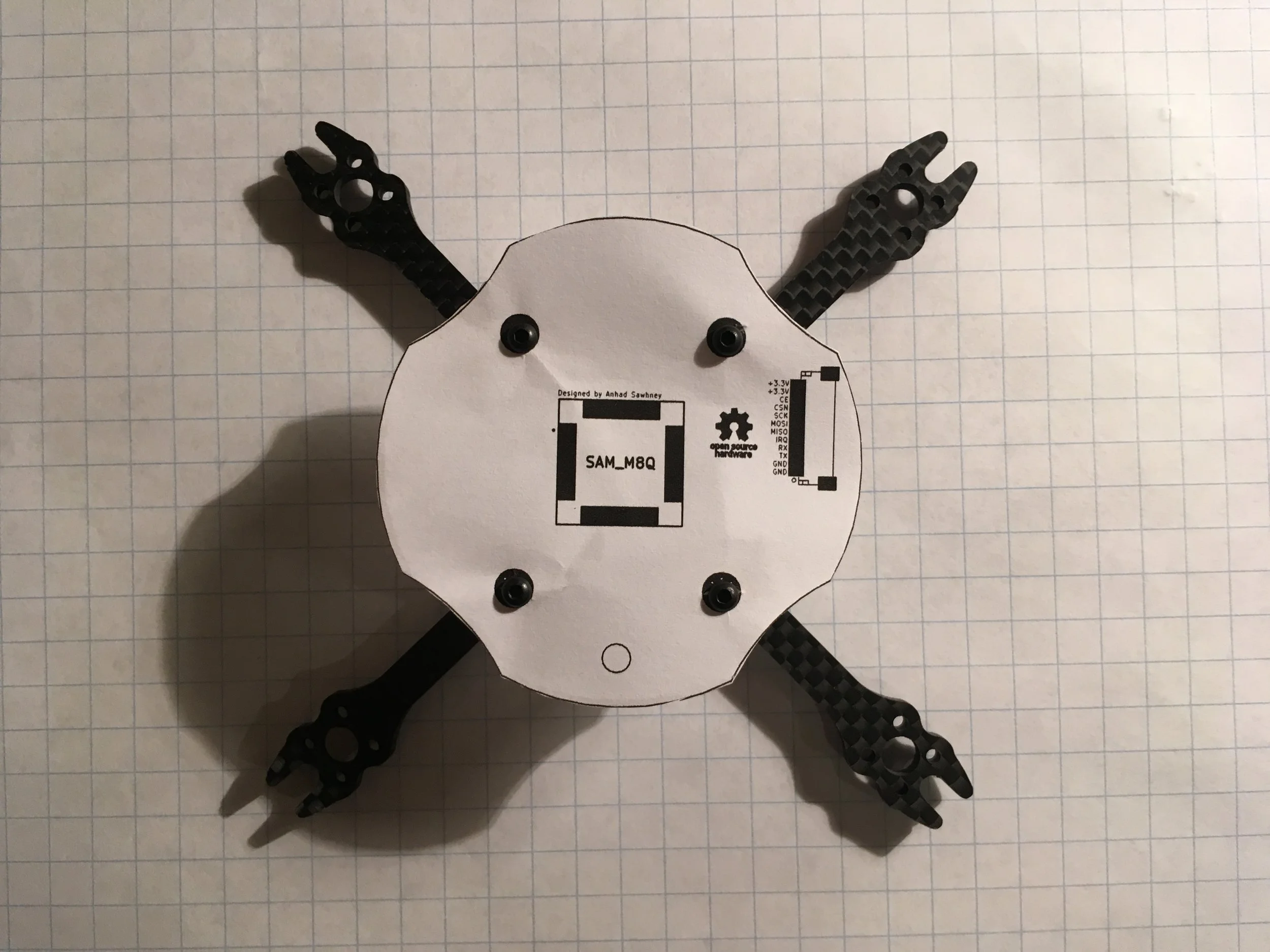
Overall circular shape with cutouts for propellers
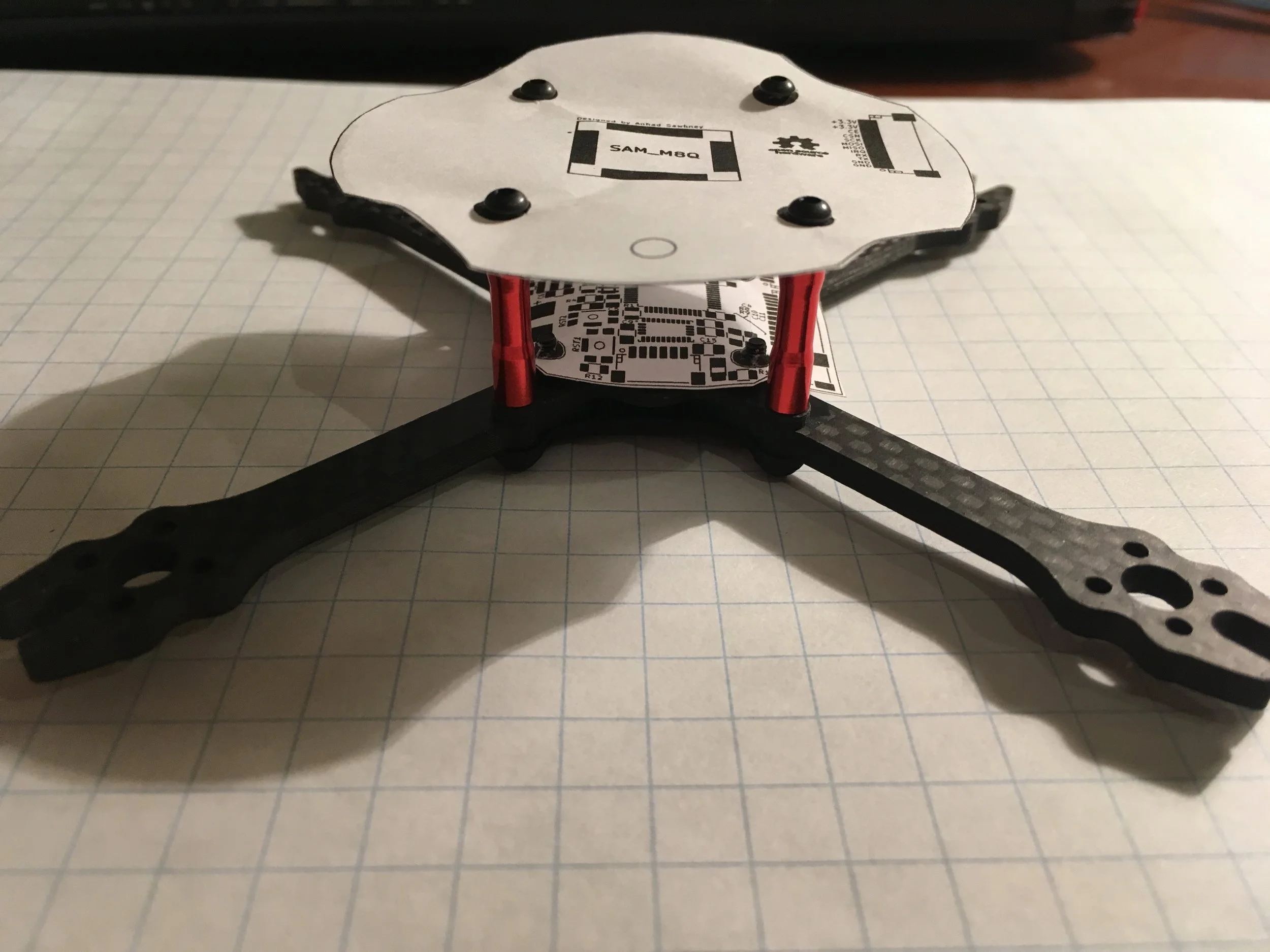
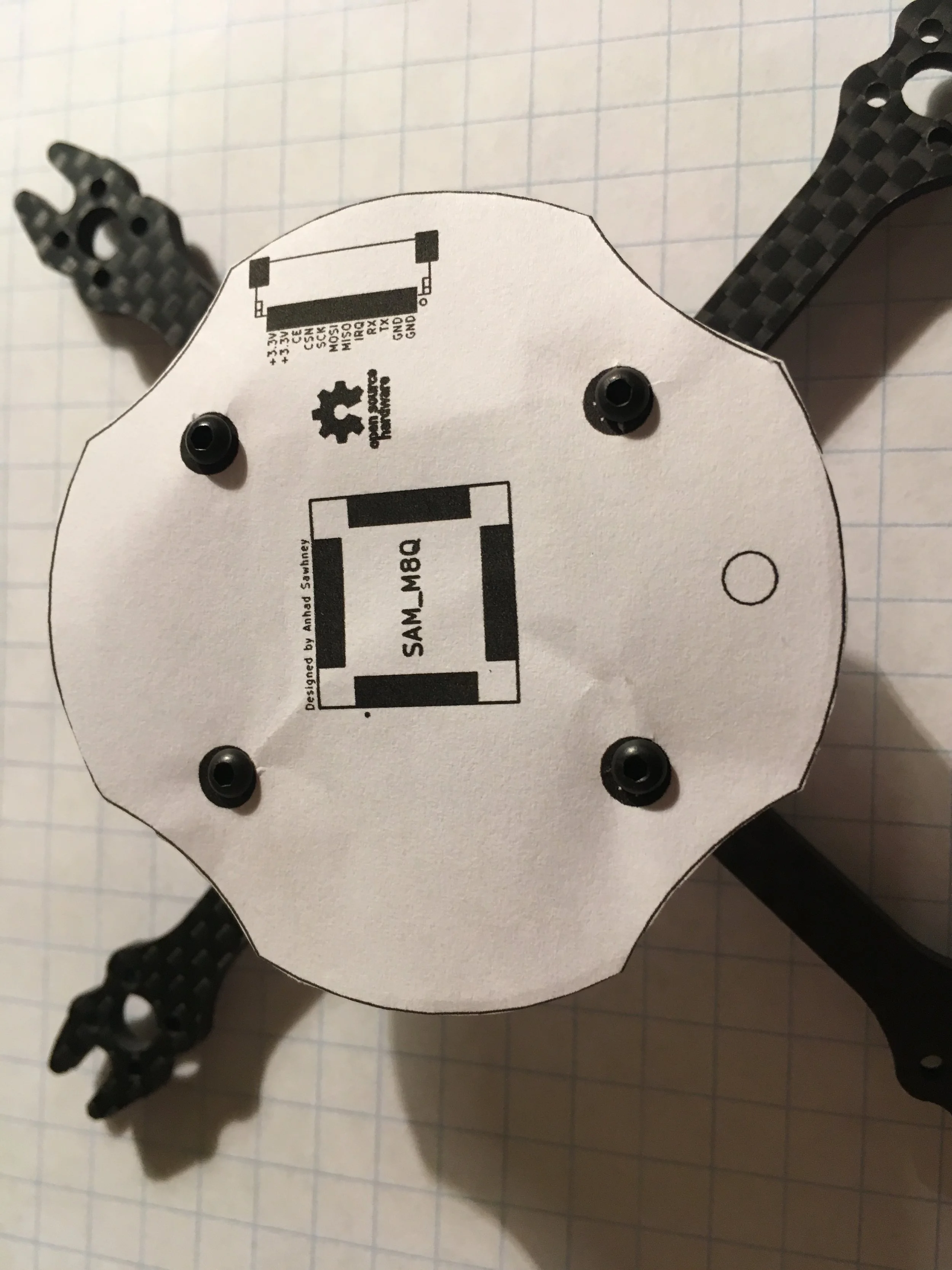
Replaces the top carbon fiber plate of the drone frame (4 screw holes)
Designed to maximize GPS accuracy and reduce noise in radio communications
GPS: Ublox SAM M8Q
With an optimal board design, this module can reach accuracies of +/- 1 meter
All of the noise sensitive radio circuitry is enclosed within the module
Unlike many others, this module has an antenna, meaning I do not have to design complex high frequency circuitry
Radio: NRF24L01+
These radio chips are present in a variety of modules. My board has support for those with both internal and external antennae
These modules are very easy to use, at the cost of being limited in their functionality. There can only be one transmitter at a time per frequency channel, although there can be unlimited receivers. (This is fine for having one base station control the entire swarm, but does not work for inter-drone communication)
The radios are mounted to the bottom of the board to reduce noise, so there is a hole in the board to allow an external antenna to stick out the top.
Connector for cable on top and bottom of board
The sellers whose cables I bought to link the boards did not specify whether both connectors would be oriented the same way on the cable. My board has a place to attach the cable on either side, so it will work either way.
Bottom Board: (Control)
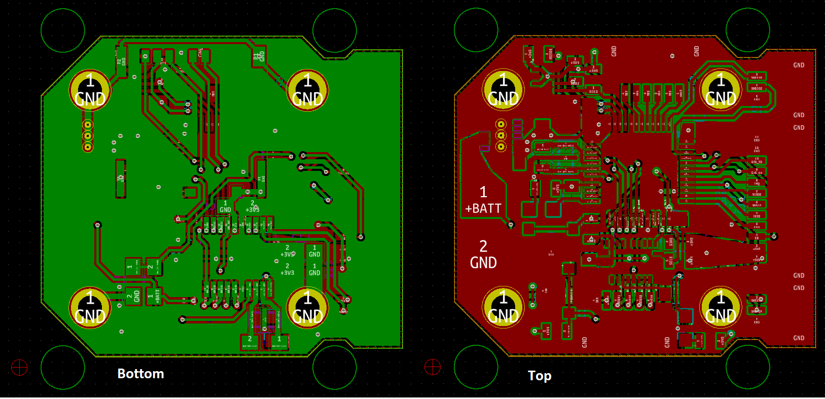
This board takes the place of a human operator and handles autonomous control of the drone. It has a variety of sensors to determine its position, acceleration and orientation in space, along with a MicroSD card which can contain a preprogrammed flight path or be used to store data recorded while flying.
There are two microcontrollers on the board. One is a dedicated low level controller (not visible since it is mounted on the bottom side), which communicates with the IMU to determine the drone’s orientation, and then alters the speed of the motors to hover in one place or accelerate in any direction. This controller will be programmed to receive and execute commands from the high level controller such as “stop / hover in place”, “accelerate upwards at 0.5m/s”, “rotate left 90 degrees”, etc. This level of control is what is commonly found in remote control drones. A human operator acts as the high level controller and sends these commands using the sticks on the transmitter. This means that code for this application will be freely available for me to use as a starting point, which is why I chose to use a separate dedicated microcontroller for this task. If I had reserved everything to a single, more powerful microcontroller, the hardware design would be slightly easier at the expense of the software being twice as hard. Microcontrollers can also only perform one task at a time, and a dedicated low level controller would not be affected by an incoming radio communication interrupting the high level controller.
The second microcontroller is the high level controller. It takes the place of the human operator, determining the drone’s position using the GPS and barometric pressure sensor, reading the stored flight path on the MicroSD card and instructing the low level controller to move the drone accordingly. Since it is not occupied by continuously adjusting the speed of each motor, the extra processing power is used to handle incoming radio communications and interface with any experiment specific attachments such as an LED, camera or other sensors.
Sensors
BMP280
This sensor measures barometric pressure and can use that data to calculate the altitude of the drone. It has an accuracy of +/- 1 meter.
It also has an integrated temperature sensor (which will probably not be used)
BNO055
This is a 9 axis IMU (inertial measurement unit) which contains an accelerometer, gyroscope and compass.
Using these sensors, it is able to precisely determine the orientation of the drone in 3d space, and the acceleration forces acting on it.
The remarkable thing about this specific sensor is that it contains a very powerful onboard processor. The readings from each of the 3 sensors within the IMU all have a certain degree of noise, but the processor can handle the calibration of all three and use kalman filters and corroborate the readings from the other sensors to eliminate inaccuracies
For some reason, this chip also has an integrated temperature sensor, which will most likely not be used.
Connectors
Communication with radio board
One for programming each microcontroller
Communication with the motor controller (Quad ESCs)
A general purpose connector so that the drone can communicate with various attachments such as an LED, camera or other sensors.
Microcontrollers
High Level: STM32F103CBT6
Runs at 72mHz, 3.3V
48 Pins
Arm Cortex M3
Programmable with Ardiuno or ARM
Low Level: STM32F042F6P6
Runs at 24mHz, 3.3V
20 Pins
Arm Cortex M0
Only programmable with the ARM toolchain
Interactive 3D Models (Left click to rotate, right click to pan, scroll to zoom)
Schematic (control Board)
Design Iterations (Control Board)


Design Iterations (Radio Board)
Paper MOCK UP
