testing of DRONE SWARM (vErsion 2):
Assembled V2:
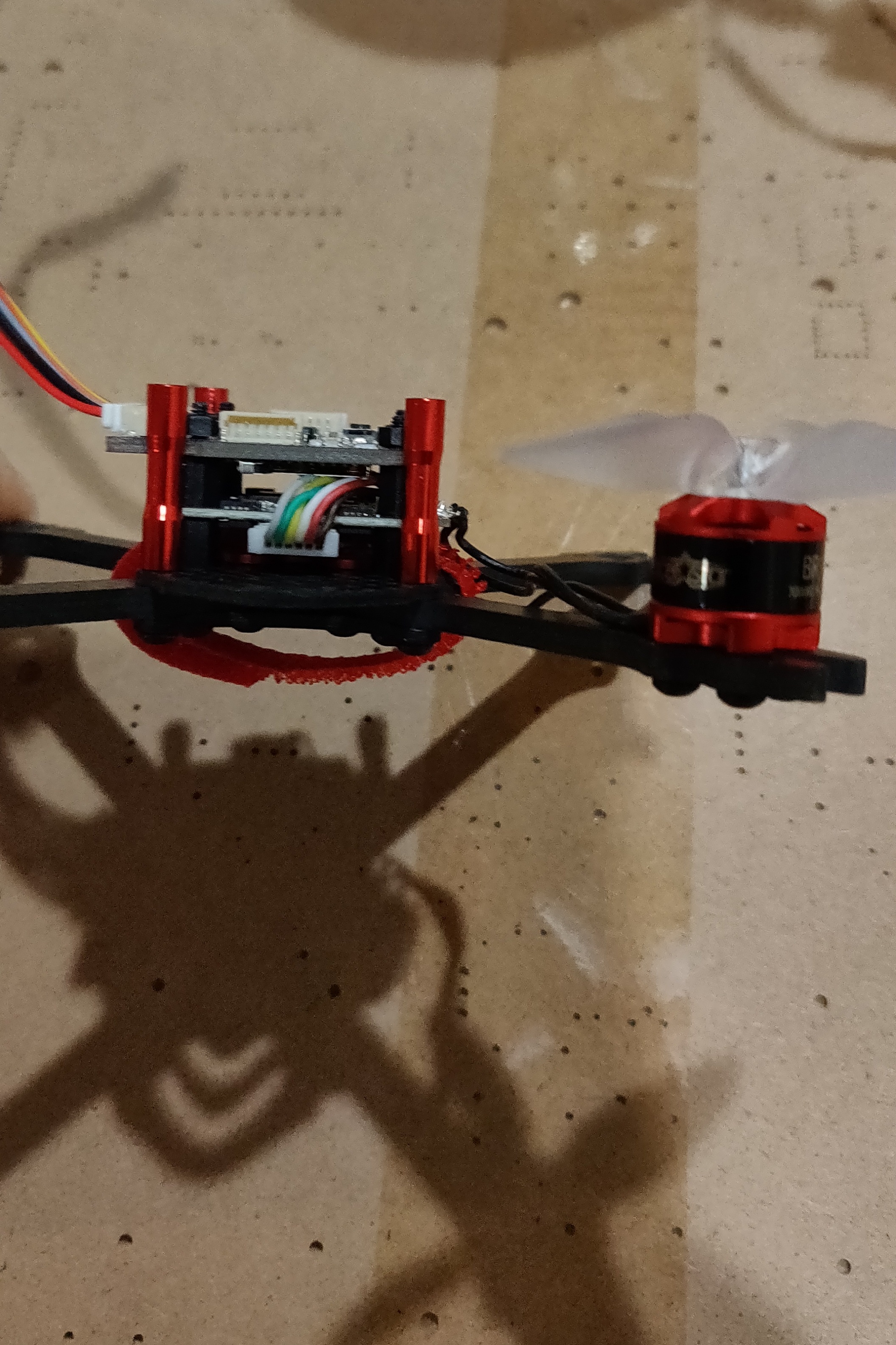
The drone was assembled only enough to test fit the boards and run one motor.


Test FIt Results:
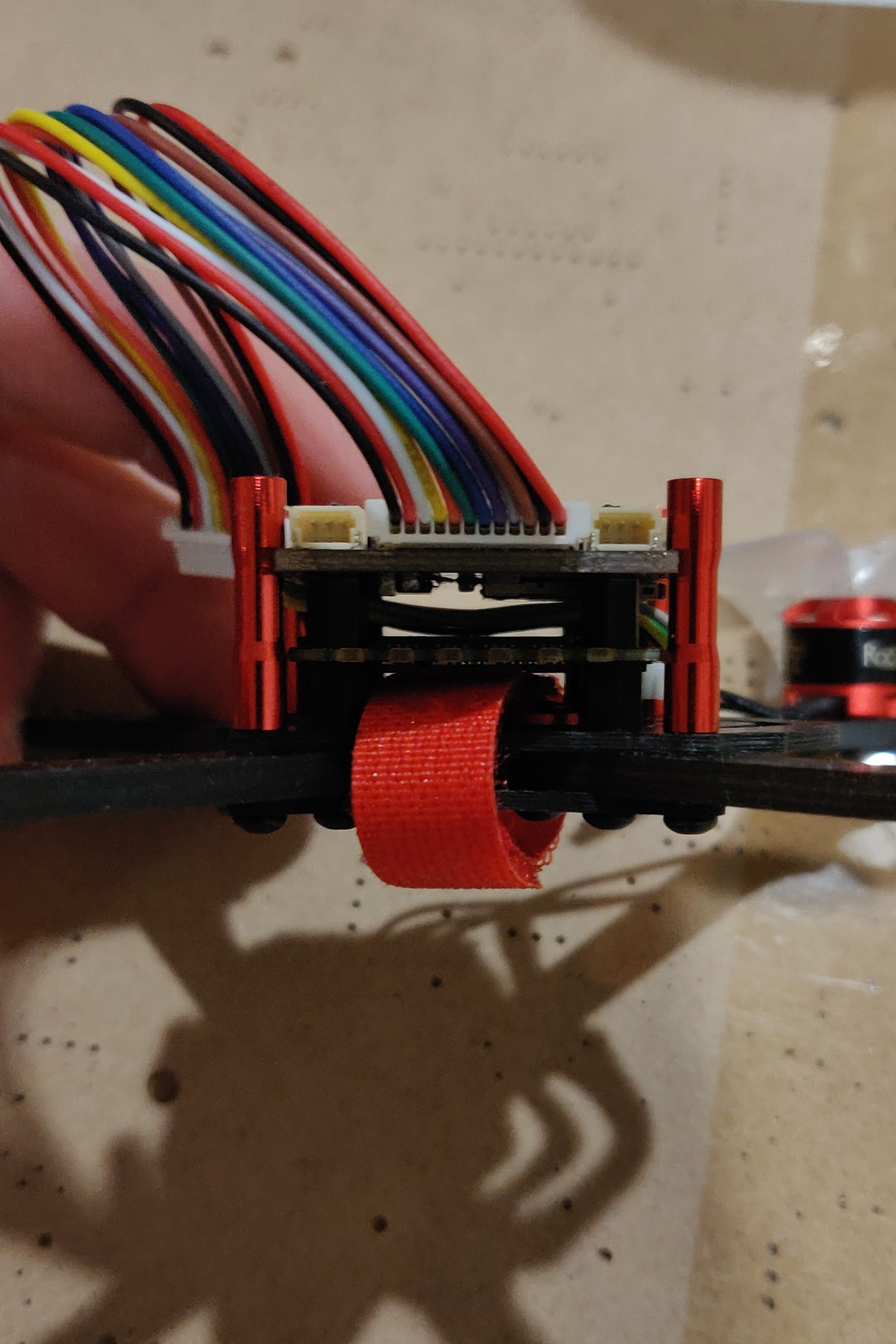
There was one spacing issue which was found when I mounted both the radio and control boards. In the picture, the drone is upside down, and one can see that the radio module will collide with the motor connector on the control board when properly mounted.

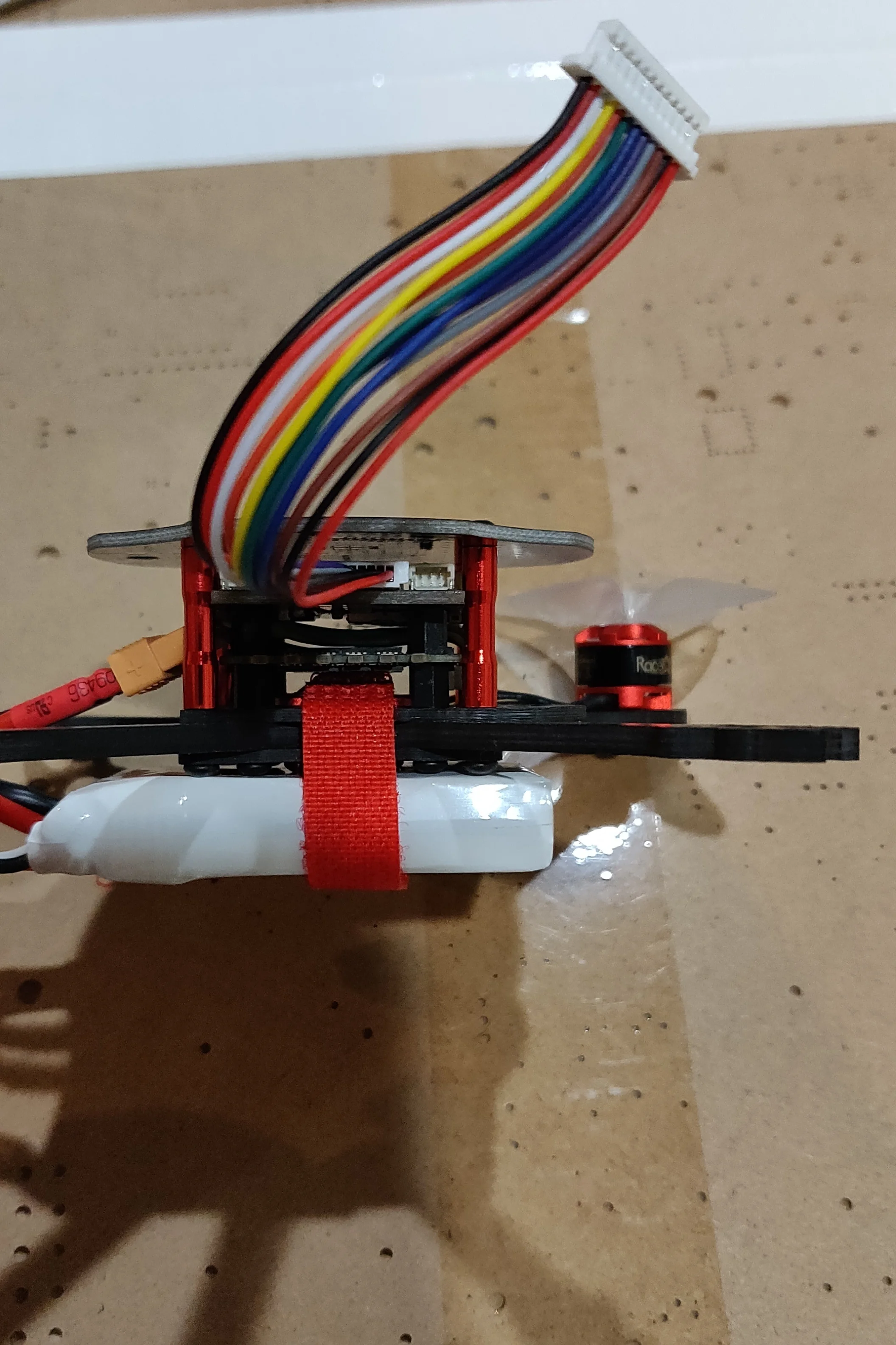
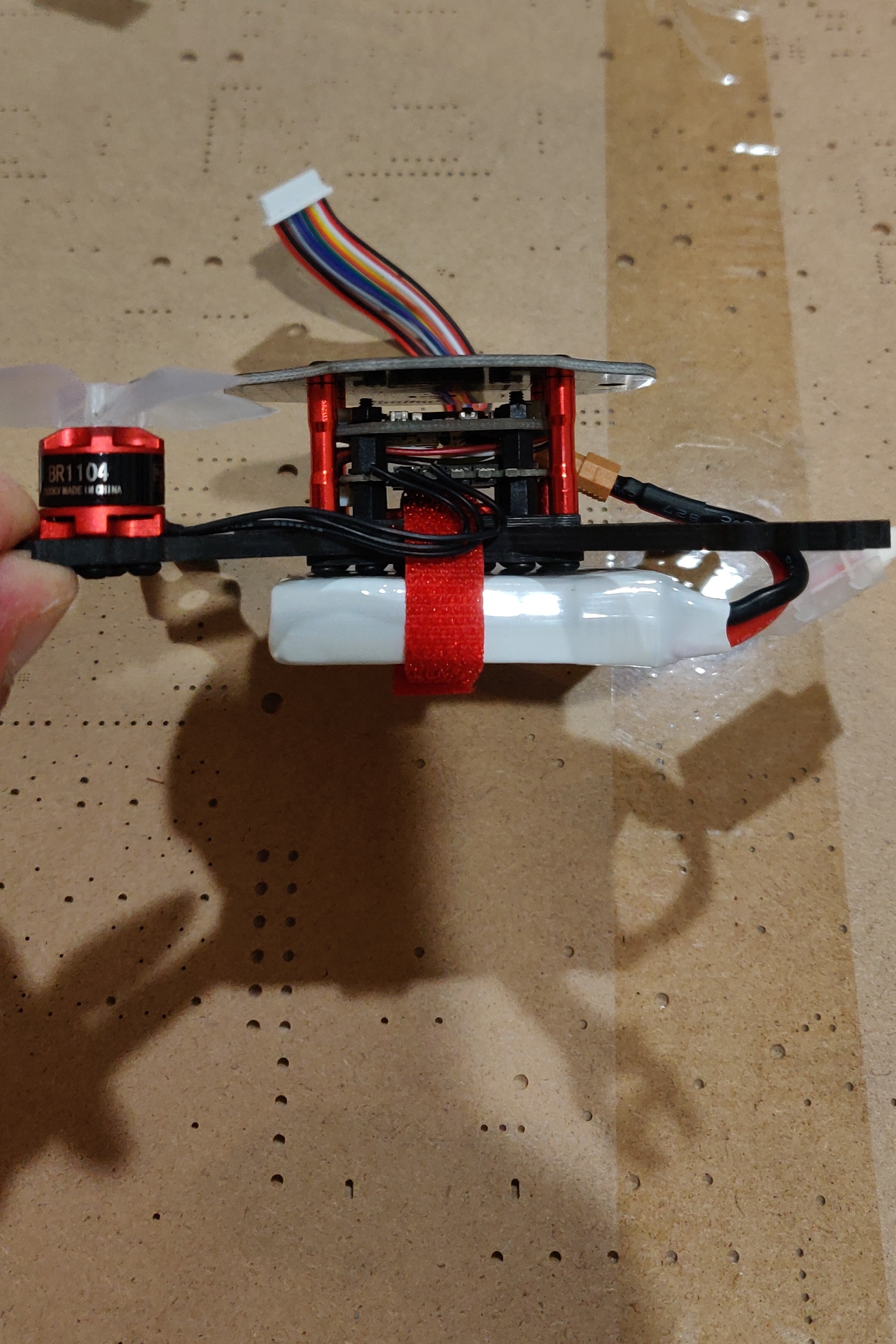
measuring the Weight:
Although the drone is not fully assembled, all of the significant components are on the scale. The remaining wires and connectors for the radio board and battery will only add a few grams. This is well within the max weight for my motor and propeller configuration.


Motor Testing:
SETUP
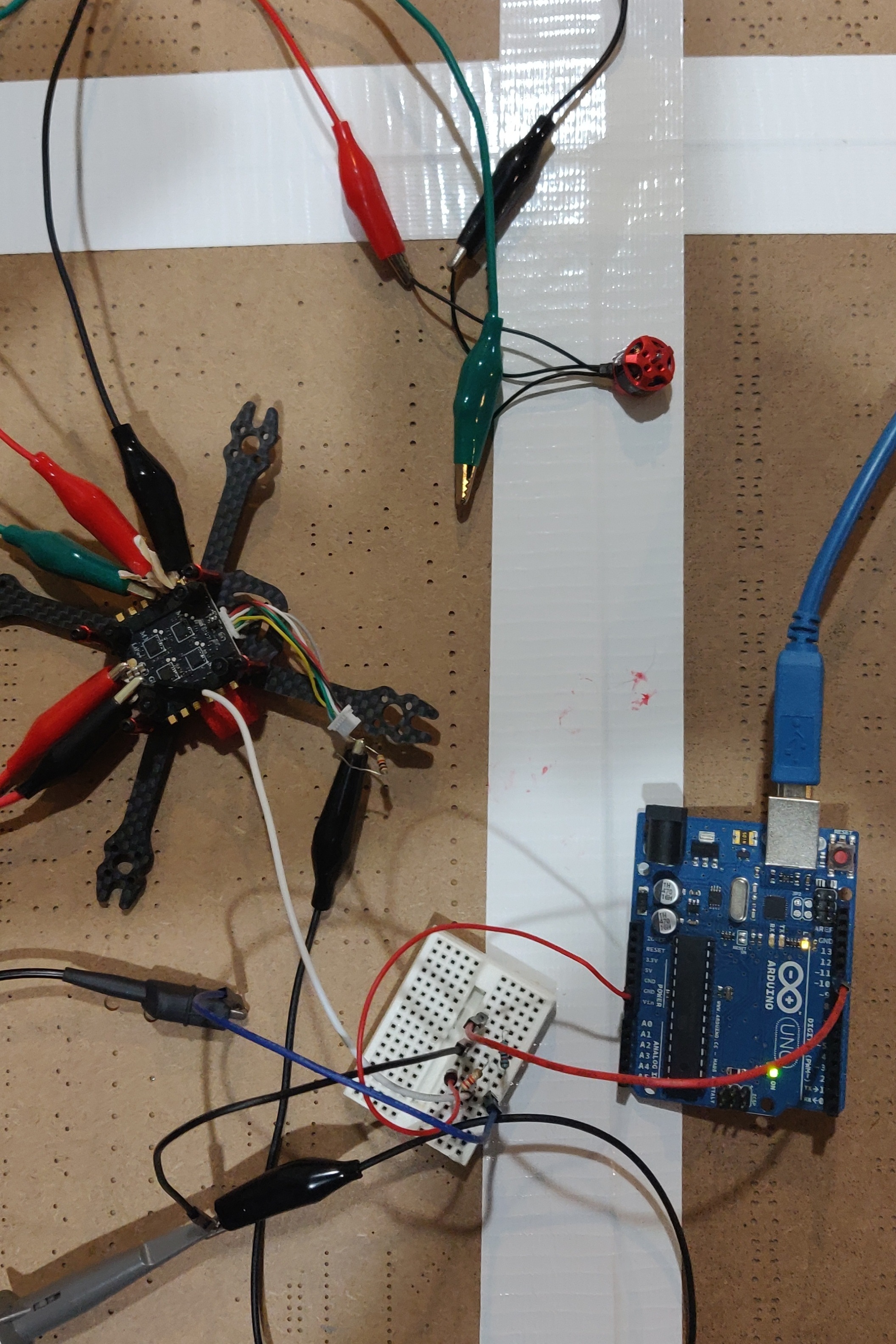
Once I received the parts and assembled them, I began by testing the motor controller with the motors. In the slideshow to the left you can see the setup.
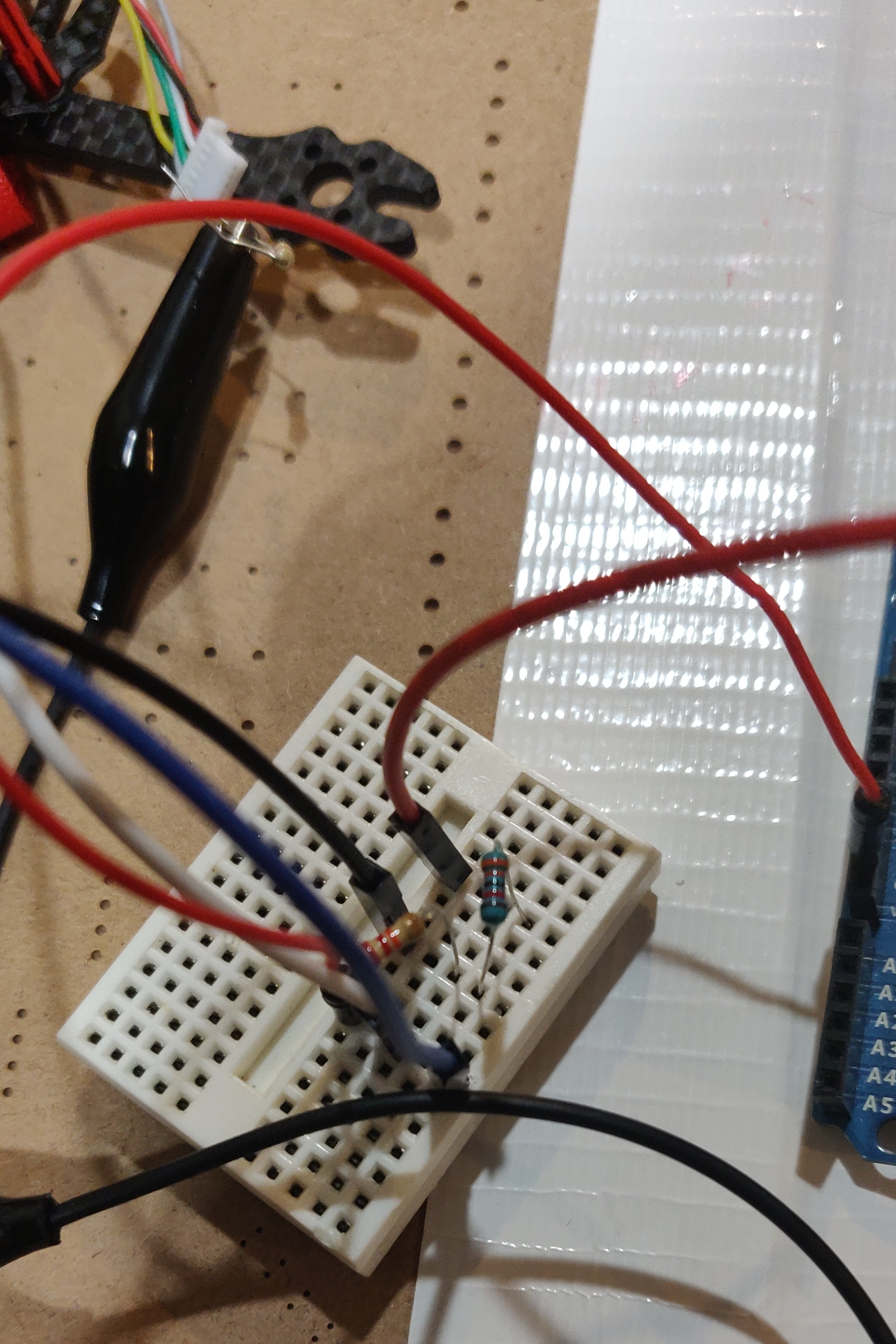
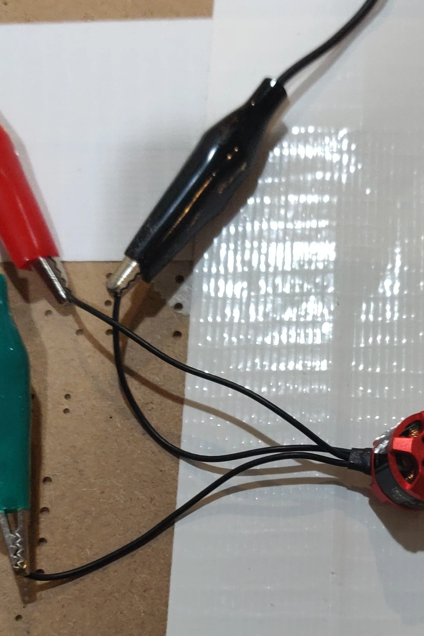
An arduino simulates the PWM signals sent from the control board. Since the version 2 control board runs on 3.3v, but the arduino runs on 5v, the signals are sent through a voltage divider to reduce their voltage. The ESC receives the signals and is connected to the power supply, which simulates a battery at half charge. The oscilloscope is used to visualize the signals the arduino is sending to ensure that they are within spec. The arduino is programmed to repeatedly sweep through the entire throttle range, so the motor should theoretically ramp up and down in speed. The motor is connected to the ESC using alligator clip cables. The motor connections on the ESC were too close together so some tape is used to prevent the clips from contacting each other.
RESULTS
During testing, the motor would move sporadically at best and often not respond at all, despite the signals being exactly as specified. The problem turned out to be that the ESC was designed to handle 5v signals rather than 3.3v. Once I removed the resistor divider, it began working normally. These results had drastic implications on the design of the drone since the version 2 control board ran completely on 3.3v.
MOVING FORWARD
The next version of the drone hardware needed to output 5v signals to control the motors. There were two ways of accomplishing this.
1. Using a logic level shifter: This solution would involve a 3rd PCB in the form of a small adapter. It would take the 3.3v signals from the control PCB and boost them to 5v for the ESC.
PROS:
Quick and easy to develop
CONS:
Inelegant solution
Another point of failure
Adds weight
2. Designing a 3rd version of the control board, which outputs 5v signals.
PROS:
Allows me to fix some of the inefficiencies and problems in version 2
Elegant solution
Allows me to use a 5v microcontroller which I am more familiar with and has existing flight controller code
CONS:
Fairly large change, since separate voltage regulation circuitry is needed for a second voltage and level shifters are needed to connect the 3.3v and 5v circuitry.